
The chapter describe how to create a workflow (including how to make use of the actions defined in the setup in the workflow – which is actually a preview to 2.2.2.)
The video is embedded by YouTube and only loaded and played from there when you click on the play button. From then on, the privacy policy of Google applies.
more examples how to create a new workflow – with increasing complexity.
Also shown:
- how to insert and split actions (which is actually already an outview to 2.2.2)
- how to change priority of robot and external axes
The video is embedded by YouTube and only loaded and played from there when you click on the play button. From then on, the privacy policy of Google applies.
Creating and naming a new Workflow #
With respect to generating workflows, you can
- Create a new workflow (from scratch)
- Copy an existing Workflow and Modify it (most efficient method)
- Import a workflow from another .ap project file
Creating a Workflow from scratch #
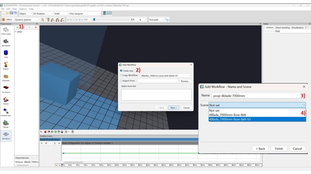
The steps to create a new workflow are as shown in the image above
- press <add> button
- chose “create new”
- name it
- select the scene (which contains the correct workpiece / part to be treated and the correct tool)
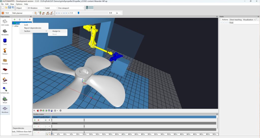
Optionally assign the workflow to a subgroup of workflows -called section
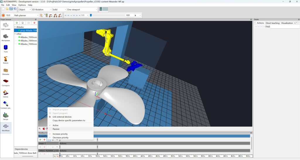
In the given example, the rotation-table of the propellor is not actively changed / controlled during the treatment. Therefore, set it to active and make sure it is the highest in the hierarchy of robots and axes and conveyors. That way, the other actors, such as robot and external axis are planned to deal with the situation defined by the rotation table – not the other way around. Set the rotation table to passive, in that way it is not actively planned by the software. Instead you define its state next.

The image above shows how to define the pose. The procedure starts with right mouse click in the field and selection of “insert point”. Edit the pose (in this case the orientation) of the
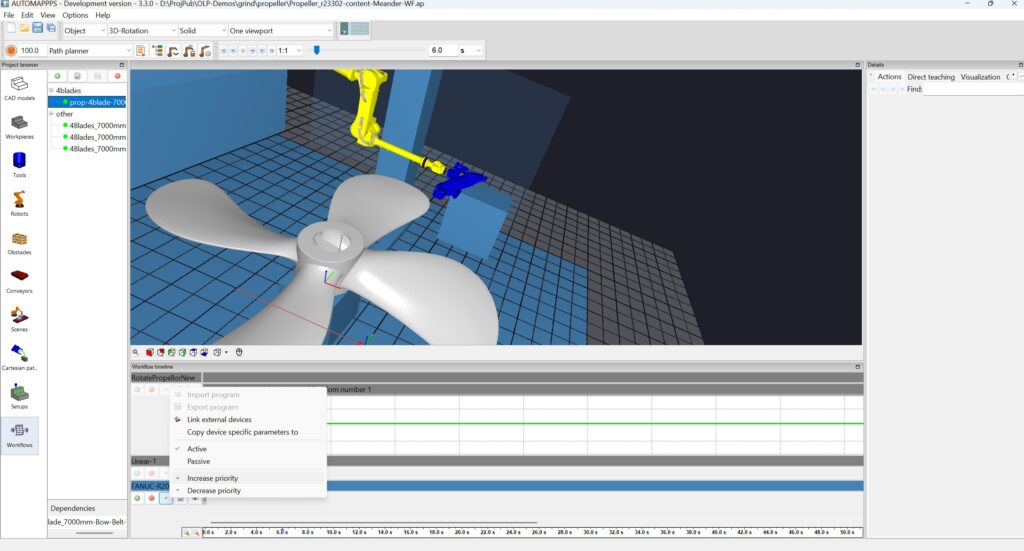
The external axis usually shall be controlled by the robot. Therefore it shall remain “active”. The robot shall be higher in priority than the external axis, since it achieves the dominant part of the motion and the external axis shall only contribute when needed for the robot achieving the coals and preferably move less (than the robot). Therefore, select the robot (click on the left field with the robots name) and increase the priority until it is above the external axis (but below the rotation table).
Copy / Duplicate an existing Workflow #
TBC
Import a Workflow from another project #
TBC
Editing planning parameters #
The planner needs parameters in order to find the solutions which are best for the process and the robot used and to find the best compromises.
Note: if you copy / duplicate or import a workflow, the settings of the original workflow are used. Therfore, you usually do not need to edit the settings.
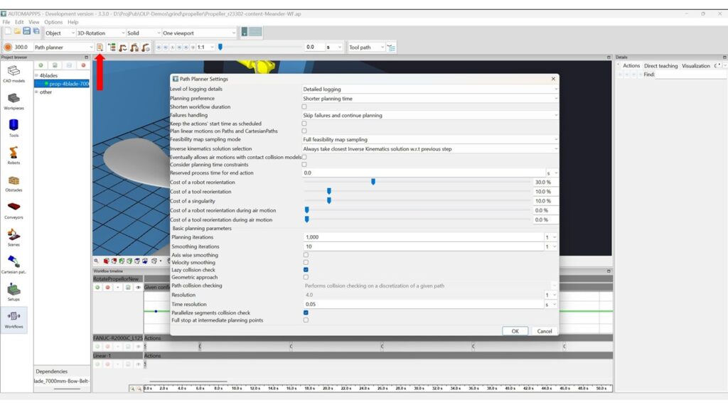
The image above shows some standard settings after creation of the new workflow.
- Level of logging details: Select how much logging information you want. You can chose settings that log only steps of significant progress and errors. You can also chose settings that log more details, including smaller steps of progress, and warnings and deviations. More detailed logging does allow to easier find “where things start to turn wrong”, not only where the got wrong.
- Planning preference: You can chose between faster planning or faster execution time.
- Shorten workflow duration: You can chose to keep the duration of the workflow as oririginally defined, or allow the planner to shorten the duration. Note: If the robot motion-planner shortens the duration, a subsequent motion-planning attempt may fail due to insufficient time for execution of the program since smallest deviations can lead to the issue that the program would need a few milliseconds more. If you use “shorten duration” increase the cycle time by a few secondss before call the automatic robot motion-planning again.
- Failure handling: You can define how the robot motion planner shall react to unreachable motion-points. Common are e.g. “Skip failures and continue planning”. In the result you will see where the planning failed (and receive an error message in the log you can click on – and often see the situation (e.g. a collision) in 3D) and also how later actions are planned. The opposit setting is “Abort planning as first failure occurs”. If you chose this setting, the planner will immediately stop. You will see the results earlier, but you do will not see if and how the robot program would continue, which can be helpfull to modify the problem case.
- Keept the action`s start time as scheduled: The planner tries to stick to the original timing of the actions and only (delays) if impossible. If timing is chosen well, this is a faster mode for planning, since no efforts for scheduling are required, but the execution time is usually a bit longer.
- Plan linear motions on Path and CartesianPath: Keep (in 99%) unchecked. If the box is not checked, the planner can use a more optimal way to plan with minimum non linear deviations from the linear path, which will however executed as a linear path by the robot.
- Feasibilty map sampling: This parameter can have a significant impact on the planning time in case of a) long paths with plenty control-points and b) if the paths are changed in the setup editor. Once sampled, a path will not be resampled unless the path or the cell changes. “Full feasibilty map sampling” means that an external axis, conveyor, or rotation table is checked for possible solutions along its entire range of motion. “Reduced feasibilty map sampling” and “Minimal feasibilty map sampling” mean that the planner searches only +- x% (will be defined per auxillary axis) around the state. The difference between “reduced” and “minimal” is only relevant if the external axis changes its pose over time. “Reduced” implies that the entire range of values the axis taskes on during the workflow (+-x%) is considered for each way-point of each path. “Minimal” implies that only the actual value taken on by the external axis “at this point” is considered.
- Inverse Kinematics solution selection: You can chose between “Always takes the closest…” and “Always takes the best”. We recommend the closest to the previous, since reconfigurations during air-motions are minimized.
- Eventually allow air motions with contact collision models: Do not use this settings, i.e. not not check the box unless for a quick check, since it will result in potentially unsafe “air-motions”.
- Consider planning time constraints: If you check this box (recommended), more choices pop up and you can limit the planning time for the entire cycle, per air-motion, per action, etc. If not, the planner will try until it runs out of iterations.
- Cost of a robot reorientation / Cost of a tool reorientation / Cost of a singularity: For several processes and for several robots controllers reorientations or singularities are not crucial. You can set how strong “malus” of a motion solution is considered compared to the benefir of achieving a solution for the action to be planned.
- Cost of robot reorientation during air-motion / Cost of a tool reorientation during air-motion. If the part of the robot program dealing with air-motion is exorted in ptp / joint-mode, a reorientation does not matter as it does during the process. In fact, you sometimes even want to reorient in order to unravel the cables. Therefore those are considered independently.
- Planning iterations and smothing iterations. The higher the value, the better and smoother motions might be found which will lead to shorter cycle times. However, the planning time increases. Also increasing planning time might exceed above defined planning-time constraints. Common values ranges from 1000 to 3000 (the latter for very complex / narrow robot motion problems) and 10 to 20 for smoothing.
- Axis wise smoothing and more: TBC
- Time resolution: Set e.g. to 0.02 and the planner checks 50 times per second for possible collisions. If the speed of the robot motion (e.g. at the TCP) is 2.5m/seconds, the tests are performed all 50mm. The minimum distance between robot/tool/part and the environmant and the surplus dimension of the ACM (air collison model) needs to be larger than those 50mm. If you have faster motions or very small tools or part or other structures (such as needles), lower the time resolution.
- Parallelize segments collision checking: Check is several segments shall be tested parallel or sequential.
Those settings are however not the correct ones for the given process. Better fitting path planner settings are presented next.
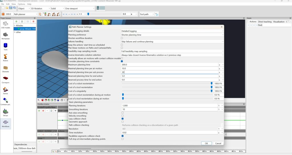
More case relevant parameter settings. The main difference are:
- Consider planning time constraints: set ON
- Reorientations of robot or tool, or singularities musst be avoided, therefore set (the malus / the punishment) to 100%
- Reduce the time resolution to 0.02 seconds.


