
Reference points are little helpers for building robot cells or programming an application. They define the coordinates (location and orientation) of points of interest.
Examples are e.g. candidates for Tool-Center-Points (TCPs). Flange points allow you to attach a tool to the robot’s flange automatically. Simulation-points define where a process-simulastion starts from a.s.o.
Reference points also define possible locations where to pick or place a part (pick points and place points). Reference points are also used to align the virtual world with the real one. Measure the position of 3 points of the workpiece with the robot in the real cell. You get 3 points in robot coordiantes. Than mark the same 3 points on the CAD of the workpiece. Later “match” the points in the CAD with the measured ones. As a result you will get the pose of the work-piece in the cell automatically – as will be described in the scene editor.
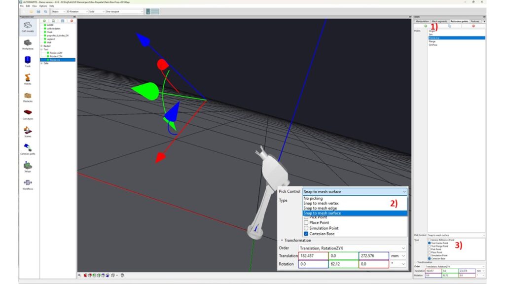
Example of reference points for the case of a painting-tool.
- 1) add a new reference point
- 2) Specify where/how you intend to initially put the new reference point. Options are from snapping to a surface, to an edge, or to a vertex, or freely.
- 3) Select the type of reference points, such as TCPs, flange-points, simulation-points or others.
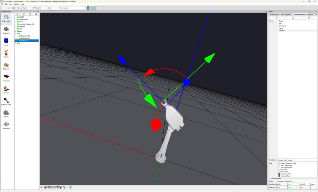
The image shows the added reference point that can be used as origin of a process-simulation, here paint-simulation.
Reminder: If you want to set a reference point graphically by clicking on a CAD-object, or if you want to modify it by selecting one of it´s coordinate-axes, don´t forget to press “CTRL”. As described in the GUI: Without CTRL all mouse actions change the view or move or rotate the object, cell, etc.


