
Tool paths or patterns of tool paths are commonly projected on the surface of the part in order to follow the surface. You can however also project those patterns or paths on limited area of the part.
In order to achieve this, you can mark several regions (also called Mesh-Segments) of the part in the CAD Model editor.
In order to do this open the “CAD Models” editor and select the part.
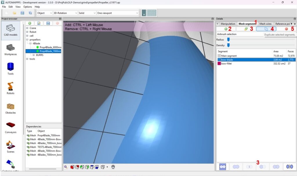
Select “Mesh Segments” (1). You can add (2) or remove (5 – or use “DEL”) those segments of the mesh, import meshed from a different project (3) duplicate a selected mesh (4 – or via CTRL-C, CTRL-C) . After you have created meshes you can use boolean operation to “merge” (create the union), create the intersection of 2 meshes, create a mesh with the combined surface except the overlapping surface, or use the first selected mesh and remove the mesh selected afterwards, or select the complementary surface.
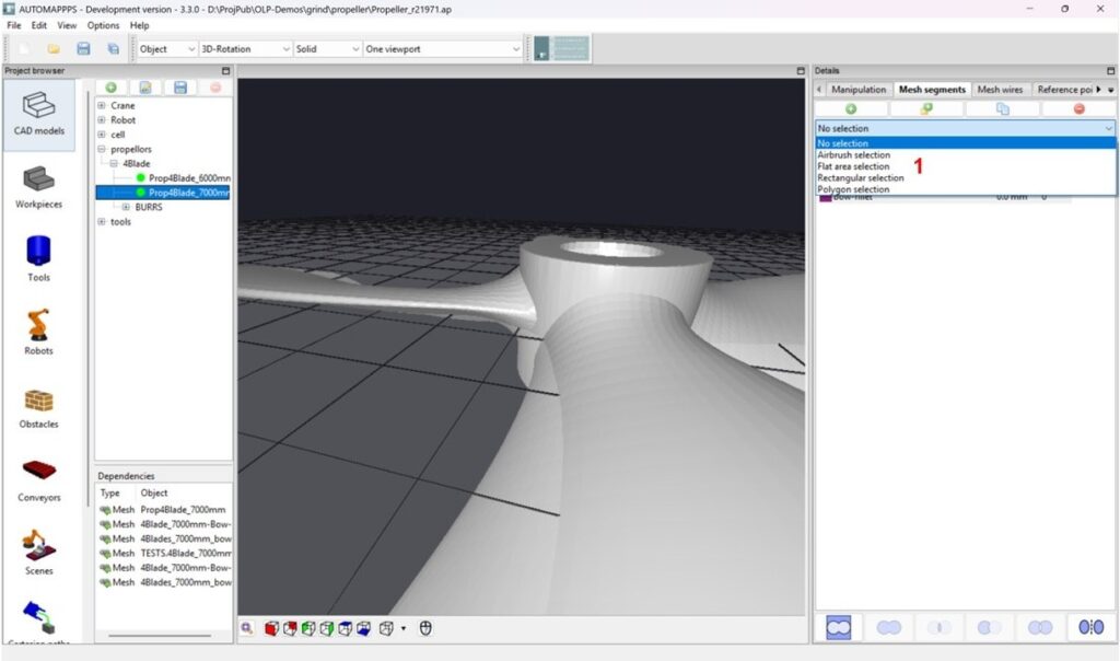
After you added a mesh, or if you want to modify a mesh later, you have to chose a method how to select or unselect the area (1). Options are “airbrush selection” (or “Flat area selection” where you click on a surface and all neighboring flat triangles are also marked. You can select rectangular selection where you set a start and an endpoint, or polygon selection, where you click on the outer points of a desired polygon shape. In case of the polygon selection, you will see the first boundatry line of the polygon after you marked the second point – not earlier.
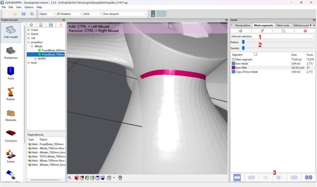
Adding versus removing surface: With the left mouse button clicked or pressed, you add area, with the right one you remove. In case of “airbrush-seelction” you can change the radius (1) and the density (3) of the “brush” that marks the area.


