
For robotics painting, powder-coating, sand-blasting, cleaning, sanding, grinding, glueing, or 3D measurement with (moving) scanners of larger areas, robot programmers employ “standard” motion patterns. The most common pattern in offline programming of robots are meanders. For those standard motions and more motions usefull for faster robot offline programming, AUTOMAPPPS offers patterns for meanders, spirals, cylindric motions, circular motions etc.
The following video shows how to apply a meander to paint a section of a commercial vehicle.
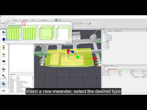
The video is embedded by YouTube and only loaded and played from there when you click on the play button. From then on, the privacy policy of Google applies.
The video above givens and overview how to use pattern in robot offline programming of painting applications. Please note: the video is not the most recent SW version, so more patters are provided. Also new patterns will extended continuously on customer request or new projects need.
Patterns for creating paths: Overview #
Several patterns are offered to create tool-paths which treat larger areas of the part efficiently.
You can initiate the pattern creation in robot offline programming in 2 different ways.
Method 1: Right mouse click at the tree-view. “add” -> “add path pattern” -> “add meander” or other pattern
Method 2: cLeft mouse click on the pattern Logo.
All pattern can be projected on the surface if the robot tool paths shall follow the surface strictly.

The patterns to chose from are:
- a: Pattern container: this is actually not a single pattern, but a umbrella for several patterns. You can e.g. assign one meander to each of the 6 sides of the reactangular block to cover all sides of a part. You can shift, modify, scale etc. all 6 meanders at once if you change the pattern container. This speeds up for example the transfer to a similar smaller or larger part. Furthermore, AUTOMAPPPS offers “fit to mesh” functions for robot offline programming or even for sensor-based automatic programming.
- b: Meander: standard meander with or without connected parallel tool-paths and definable parameters such as distance of paths, angle between paths, a.s.o.
- c: (Stepweise rectangular) spiral meander: This patterns creates spiral motions, e.g. to paint a box from the inside or outside. Path can be continous spirals, or the spiral motion can be stepwise forward and after 360 degree backwards – which is necessary if cable limits do not allow the robot wrist to rotate too much. The spiral motion can be rectangular, rectangular with rouded edges – and – if you set the rounding radius to 50% of the size, it forms a circle.
- d: U pattern: This meander can be seen as the transtion from meander to spiral meander. You can e.g. paint boxes in a U shape or in a L shape.
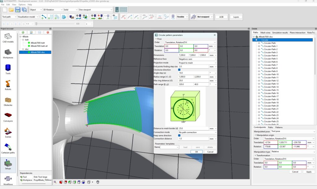
- e: Circular pattern: parallel tool paths are created in circles starting at a give radius and with a distancen between the circular paths. You can define start and end angle if you only want to treat a section of a full circle with your robot, or want to split the robot offline programming into different parts.
- f: Cylindical pattern: This patterns is e.g. to treat a cylinder, shaft, boss, and so on. The patterns can be oriented along the cylinder axis or orthogonal. The distance between paths can be define in mm or degree. The cylinder shapes can also be elyptcical.
- g: Radial beam pattern: This pattern creates robot tool paths which are starting from an center and spread like rays of a star. You can define the radius the paths start and end.
Option a: Pattern container #
TBC.
Option b: Meander #
TBC
Option c: spiral pattern #
TBC
Option d: U-shaped pattern #
TBC
Option e: circular pattern. #
There are 2 ways to start working with patterns.
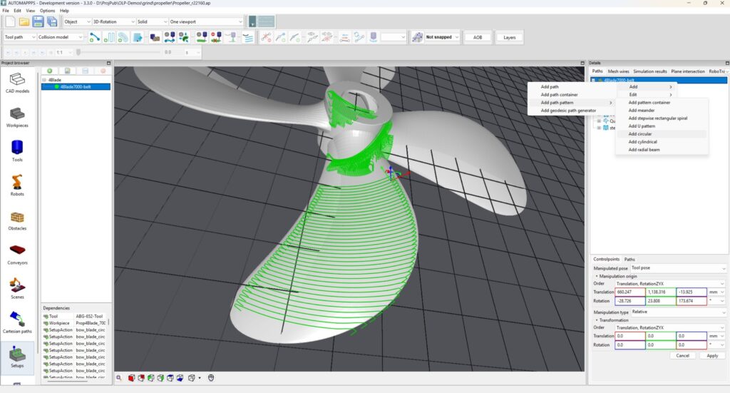
The image above shows the tree-based method: Select an entity in the tree-view (right of the 3D view), usually the root-entry and select (using right mouse click) “add and “Add path pattern” and “Add circular” (pattern).
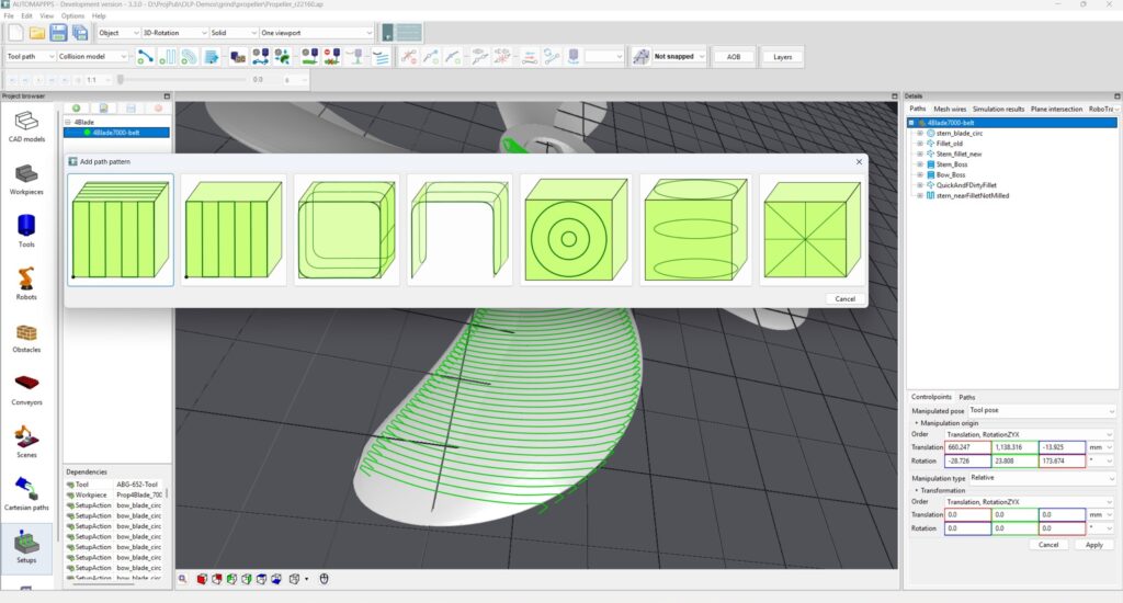
The image above shows the alternative method: click on the “Meander” button in the tool-bar above the 3D view. Select the pattern you want.
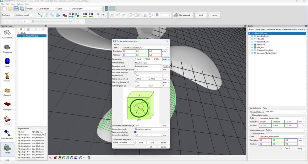
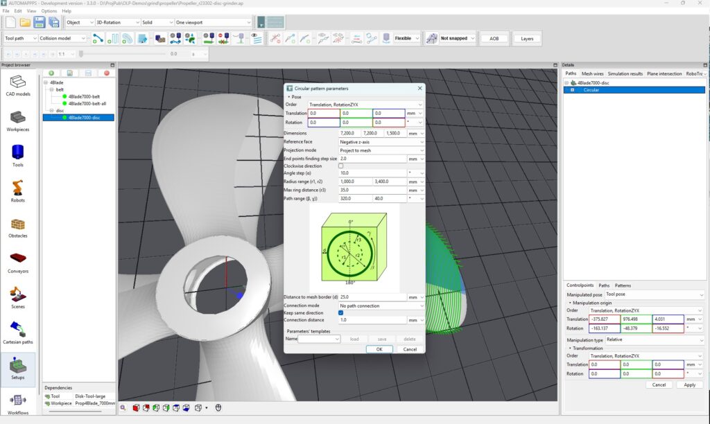
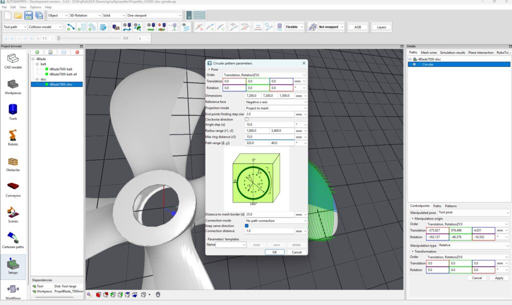
Modify the parameters of the pattern (here the circular meanders as you need) via “edit circular parameters). The parameters are (from top down)
- The Pose: the center of the pattern – and of the box which hosts the pattern (see image below – the yellow box).
- The Dimensions: the size of the box (see below) and consequently the maximum size of the pattern
- The “Reference face”: From which side (of the pattern box) is the pattern projected, or applied.
- The “Projection mode”: The final paths generated by the pattern can be projected on the surface of the part (“Project to Mesh”), limited by the surface of the part (“Restrict to Mesh”), ignore the shape of the part (“No Projection”)
- “End Point finding step size”: When projecting or limiting to the mesh, the point a path starts and ends is found by sampling a projection to the surface. This parameter definde the resolution.
- Obviously the path can be treated in a “Clockwise direction” or otherwise counter-clockwise.
- The “Radius Range” defines the minimal and the maximal radius of the circular pattern.
- The “Path range” defines the mininmal and maximal angle of the “pizza-slice”
- “Max ring distance” defines the target distance between two adajcend paths of the pattern.
- Distance to mesh border defines the gap between the surface and the start or end of the path of the pattern. This is e.g. importang for grinding to not get too close to the edge. The accuracy the border of the mesh is detected is defined by above value “End points step size”
- “Connection mode”: the individual parallel circular paths can be unconnected “No path connection” or they are connected straight (“sharp path connection”) or rounded (“smooth path connection”)
- “Keep same direction” is chosen if a paths shall be treated in the same direction – not up and down.
- “Connection distance” defines the size of a gap in the (marked) surface the path is bridging. If the gap is larger than the value, a paths is split in two paths.
- Finally, you can save the parameters of a pattern (name and save) and use (load) later for another pattern.
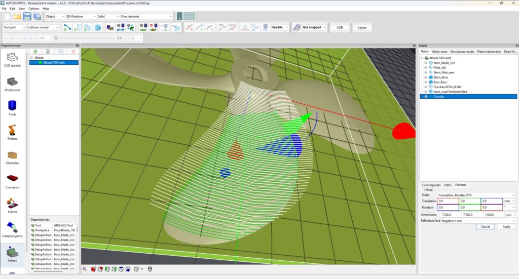
If you click on “Patterns”, you will see the bounding box of the pattern (yellow), the non projected pattern (white) and the projected paths on the surface (green). You can also edit and modify the (yellow= bounding box.
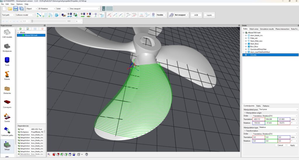
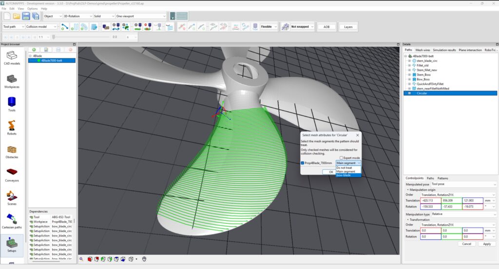
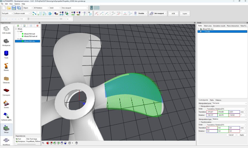
The image above shows the path resulting from the pattern (selected is “Controlpoints”)
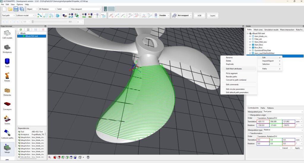
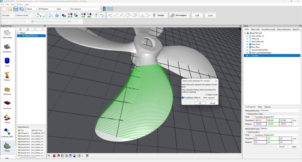
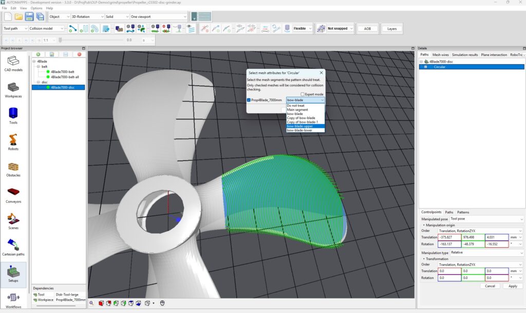
You can change the mesh that is used for projection via “Edit – Edit Mesh Attributes”
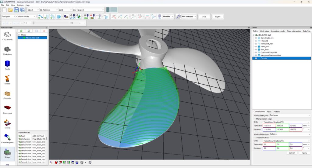
Image result after changing the associated mesh from “Main” to “bow-blade”. Please note that the paths end with the marked “bow-blade” – not with the edge of the full propeller – blade.
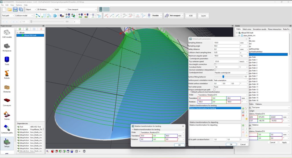
You can “edit – edit default parameters” for the selected pattern (right mouse). The parameter from top down are:
- Sampling Distance: If two defined “control points” of a path are more distant than the sampling distance, “way-points” are inserted. At control-points and way-points, the surface is sampled and a point of the path is inserted, refering itself to the surface orientation of the part at this point.
- More parameters
- More parameters
In the image above, the landing motion (approaching motion) is defined. In this case shown in the image below, one addition Landing point is added 40mm behind and 105mm above the last control-point on the surface.
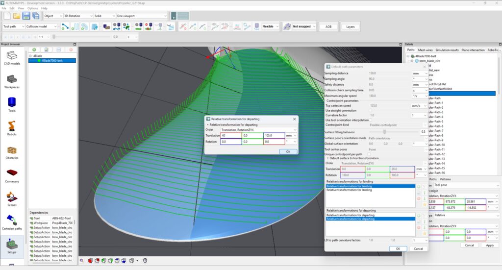
Adding a second departing point.
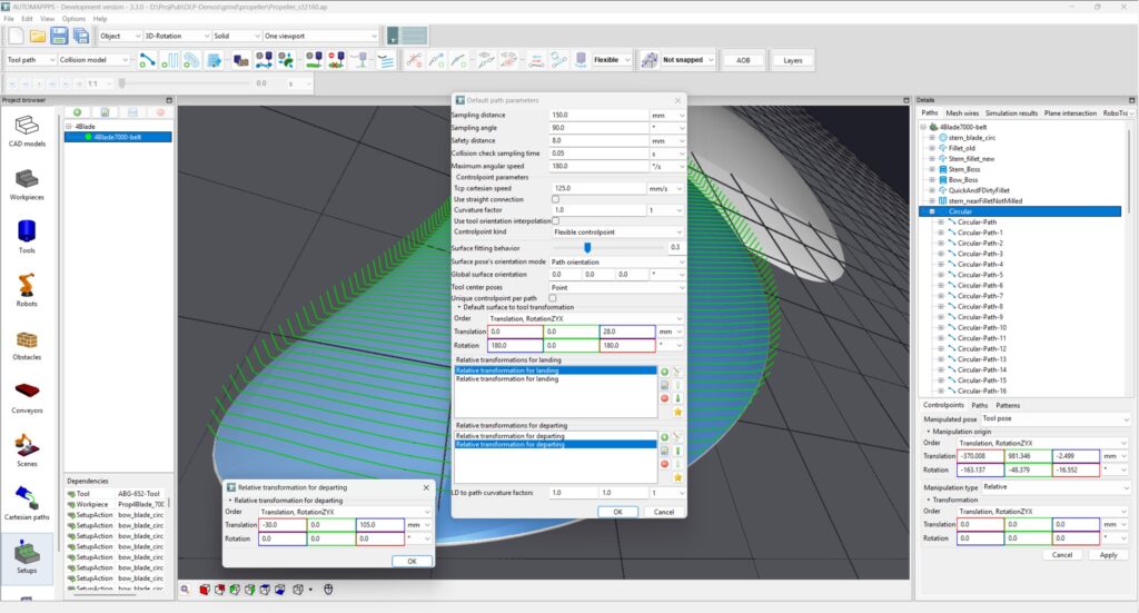
Modifying the second departing point.
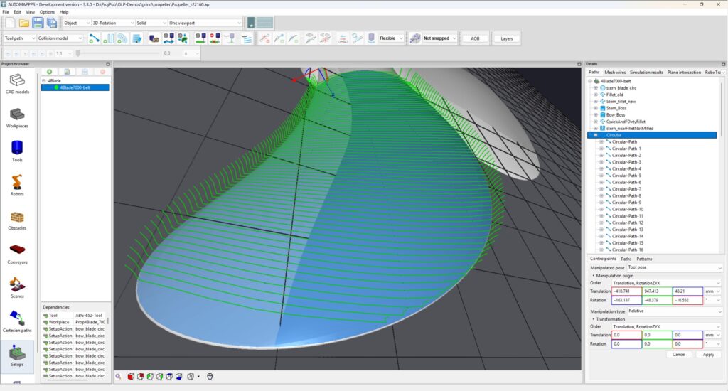
Above image shows the newly generated paths after modifing the landing and departing point of the paths.
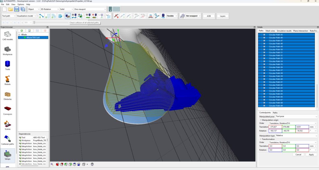
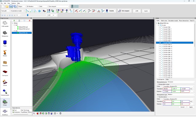
You can select one or all paths or patterns to check for collisions using the button in the tool bar above the 3D view.
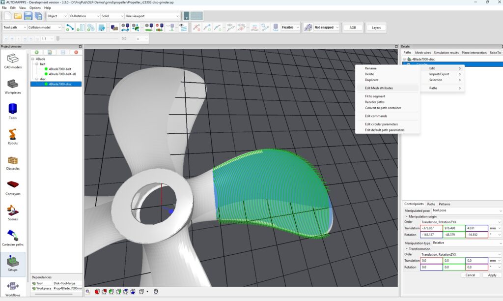
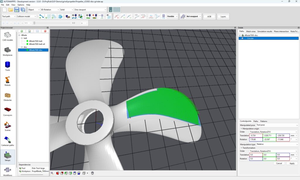
Example 2: Disc-Grinder #
..
..
..
..
..
..
..
.
..
..
..
..
Option f: cylindrical pattern #
TBC
Option g: Radial beam pattern #
TBC


