
This section describe how to (initally create and) modify tool paths of the robot on the level of complete paths and individual control-points that define the path. Graphical modification and editing the values is described as well as mirroring, translating, rotating complete tool pathes. Similar is done on the level of patterns, e.g. meanders.
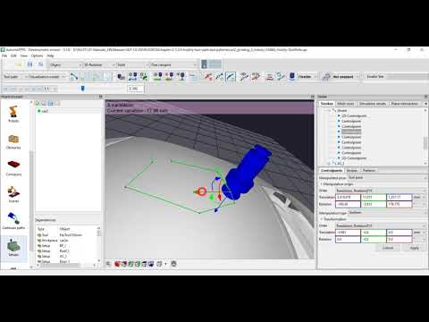
The video is embedded by YouTube and only loaded and played from there when you click on the play button. From then on, the privacy policy of Google applies.
Modifying tool-paths #
Modify complete paths #
Standard translation and rotation all control-points of paths #
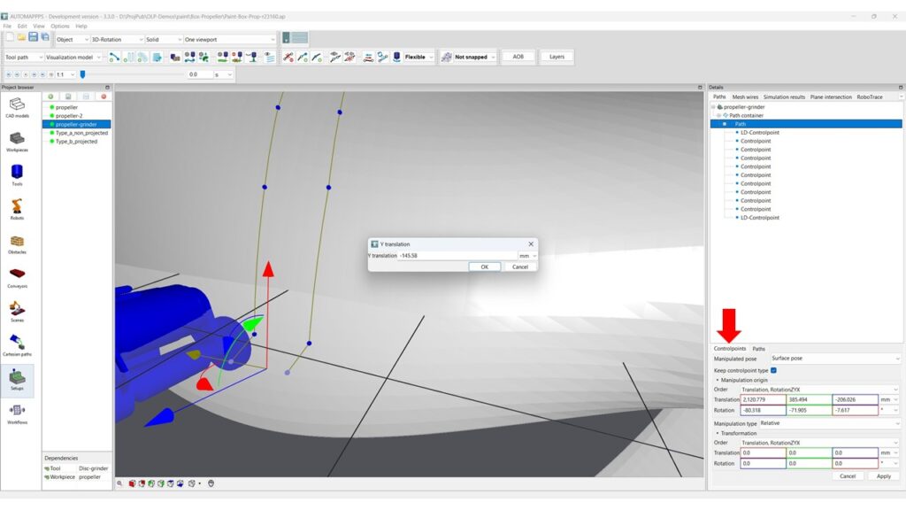
Modify complete paths
Method 1: Click on the path either in the tree-view or in the 3D-view to select one path (or multiple). The image shows the situation after selecting on of the coordinate systems arrows (translation or rotation) using CTRL.
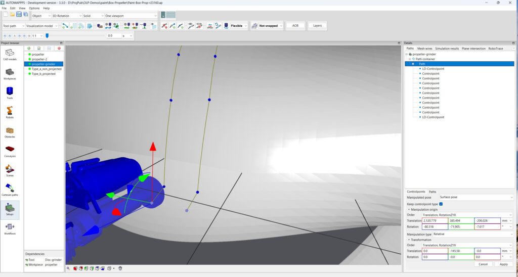
Image after executing the shift of the complete path.
Modifying (Mirror, rotate, shift) on path level #
In addition to the modifying the paths via (all of) its control-points, the path can be modified in its entirety.
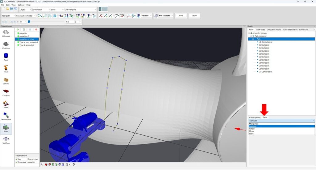
The avialable modifications are:
- Manipulate (rotate and translate)
- Translate
- Rotate
- Mirror
- Scale
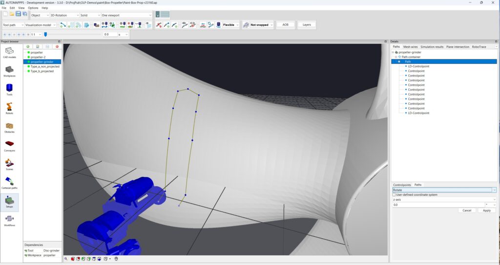
All manipulation of the path can be done with respect to 0,0,0 or to a user defined center. Usually the center of the path or one control-point of the path.
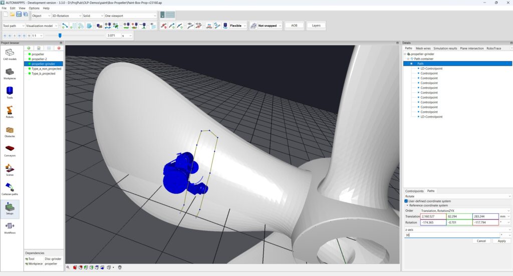
Example of rotating around the Z axis of the selected control-point be 30 degrees.
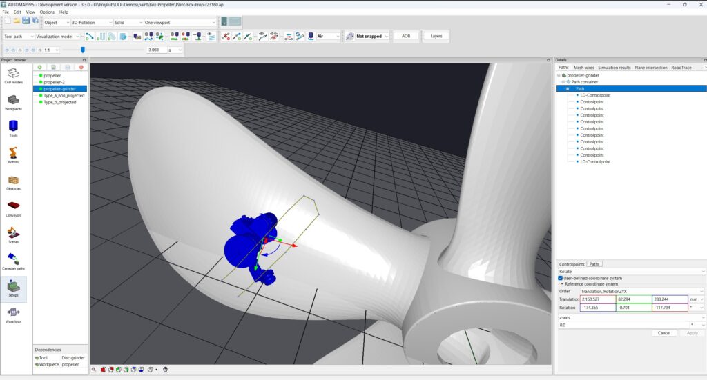
Result after rotating the path (not each control-point of the path as described before) by 30 degree.
Modify selected control points of a path #
You can modify the control-points in several modes:
- Surface pose: modifying the pose in 3D pose of the tool-tip moving strictly attached to the surface beneath. This is the most common modification for contact processes.
- Surface to tool transform.
- Tool pose: modifying the 3D pose of the tool-tip without any consideration of the surface beneath. This is the second most common modification mode.
- Flange pose: modifying the 3D pose of the flange without any consideration of the surface beneath
- Flange pose: modifying the 3D pose of the simulation point
- Path oriented pose.
Modification in surface mode #
Select “surface pose” as manipulation mode.
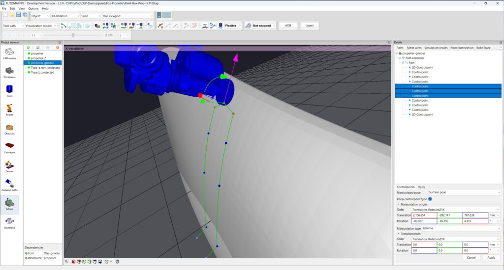
Select one or more control points in the 3D view (using left mouse click and CTRL) or in the tree-view (left mouse and SHIFT). Click on the arrow you want to pull or push.
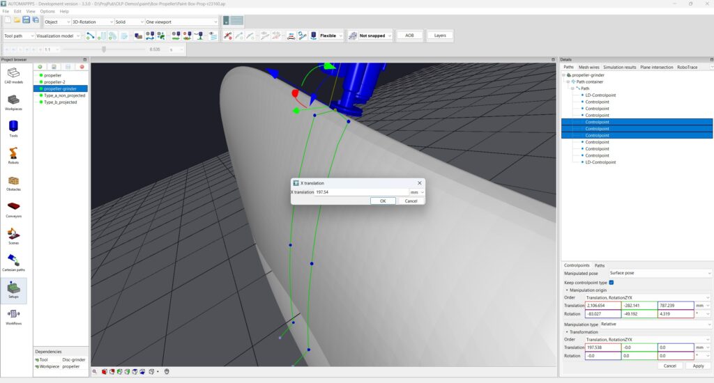
Result after pulling the 3 control-points in X direction in surface mode. The control points and the connecting paths are moving on the surface and changing the orientation accordingly. Following the surface is only working to a certain level.
Modify in 3D tool mode #
Change to tool pose and select the same 3 control points.
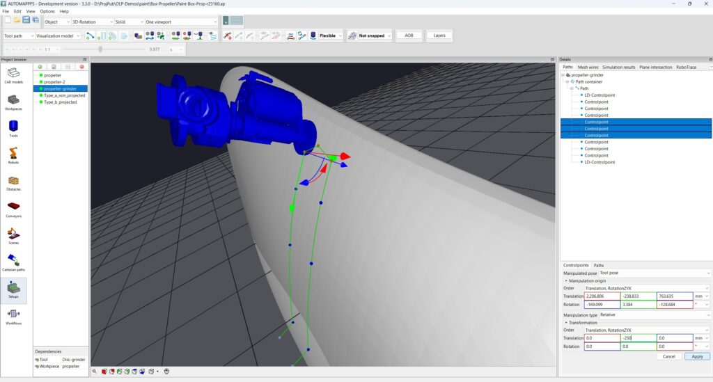
Pull the points.
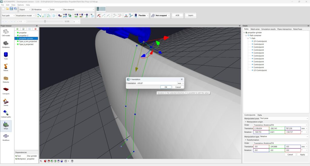
Result after pulling the 3 control-points in X direction in tool mode. The control points and the connecting paths are moving straight in 3D – ignoring the surface of the part.
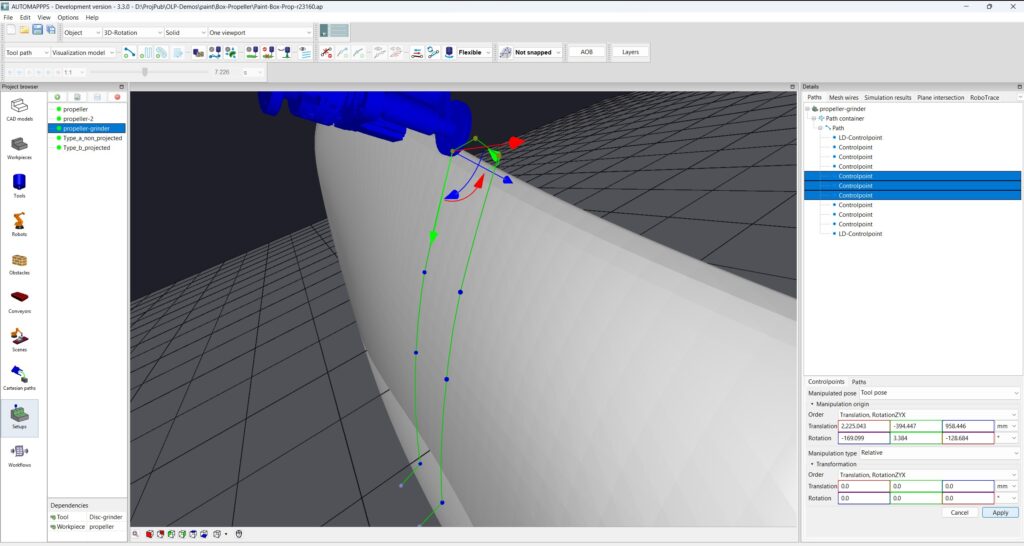
Press “Apply” to make the chance permanent. The changes can be reverted with “Edit” -> “Undo” or <CTRL> <Z>.
..


