
Robot sanding, painting, grinding, sand-blasting, glueing (aera), or 3D measurement processes with (moving) scanners are examples for “line-based-processes” (or spline-based-processes) since the tool is moving during the process with respect to the surface or “across the surface” of the part.
Robotic deburring, welding, sealing, etc. are also line or spline-based processes, but since they are tied to a feature, such as an seam or weld, other simple methods are provided in AUTOMAPPPS and will be described individually.
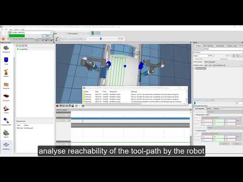
The video gives and overview how robot tool-paths can be created easily by “clicking on the surface” of the part.
The video is embedded by YouTube and only loaded and played from there when you click on the play button. From then on, the privacy policy of Google applies.
Creating a robot tool path #
There are two methods to create a paths from scratch
- right mouse click in the tree-view. “add” -> “add path”
- click on the path creation button
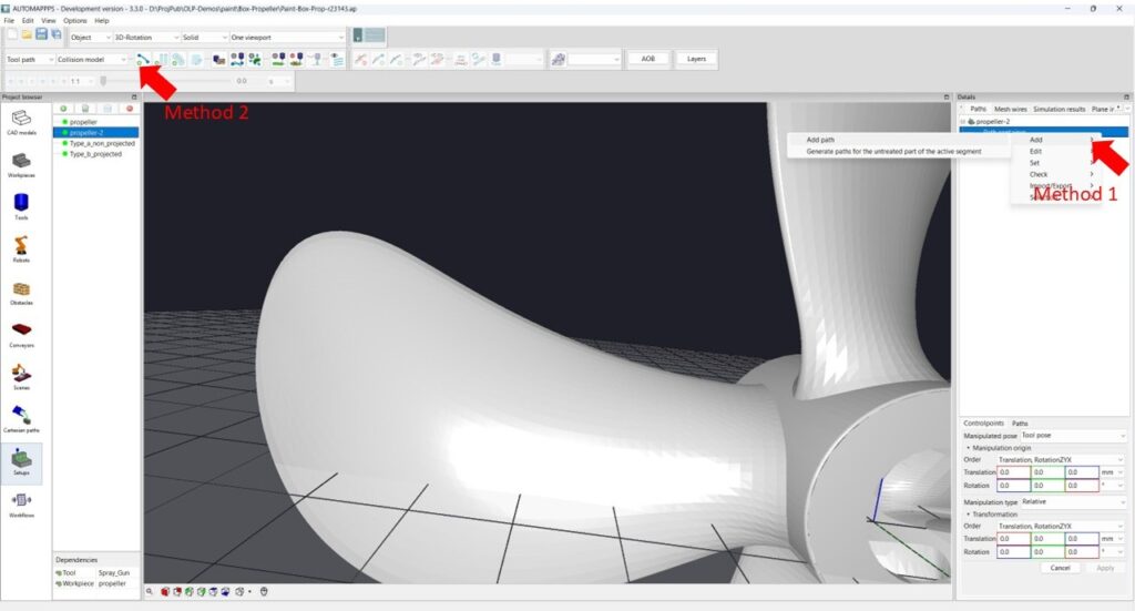
Once the path is created, it is “active”. By clicking on the part in the 3D view with “CTRL”, you do set a new control points of the path. (Remember: without “CTRL” you do not control the application but you modify the view only.
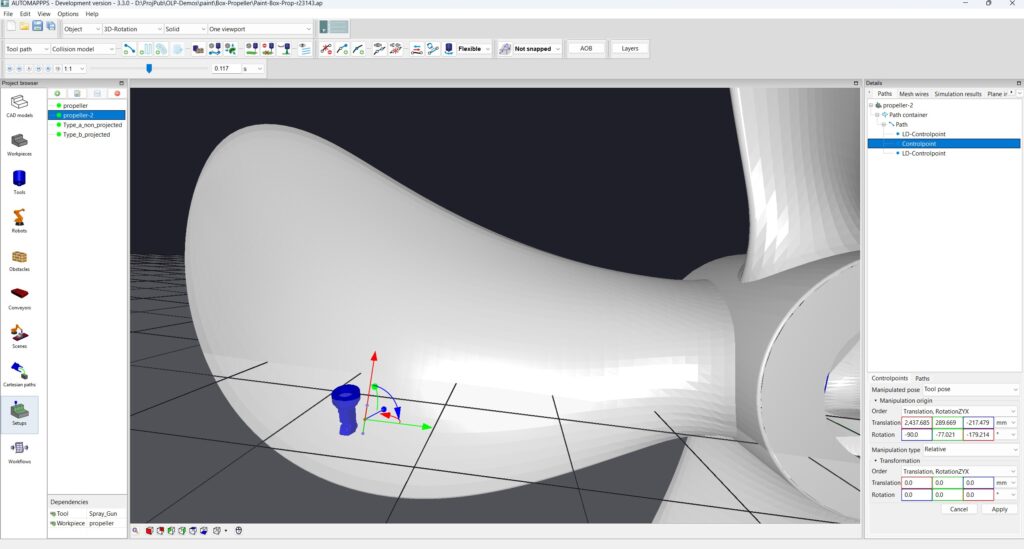
With the first click, the first control-point of the path is set. Since there is no direction, the orientation of the tool is random.
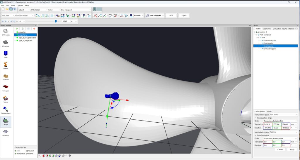
Continue clicking to define more control point. With more points, finally a linear or curved motion is defined and the orientation of the tool is therefore defined as well.
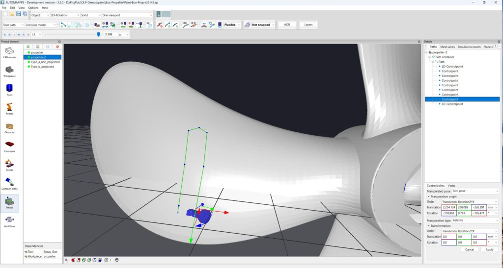
The path is now defiend. You can later extend the tool-path if you select the path again and click (with CTRL). You can modify the path, individual control-point of the path, its position, or its parameters such as the orientation-behaviour of the tool, roundness, surface following properties, tool-speed, and many more properties.
Path parameters #
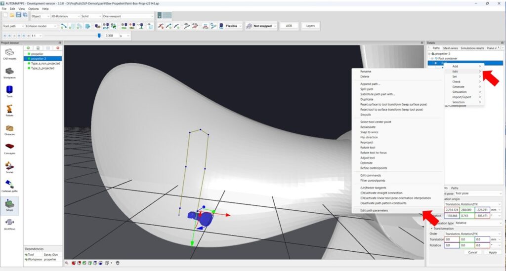
In order to modify the robot tool path parameters, right mouse click the path in the tree-view and follow the mene “edit” -> “edit path parameter”.
Tool orientation #
The tool orientation along the path, i.e. the behaviour / mode of the tool with respect to the surface of the part is defined in the “surface pose orientaion mode”. You can chose among the following mode / path following behaviours.
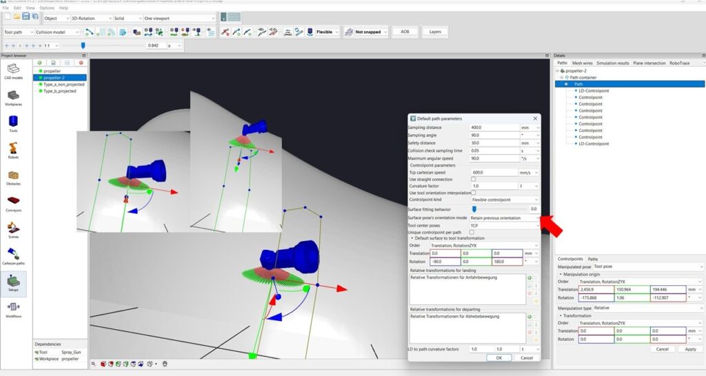
Option Retain previous orientation. The tool keeps or freezes – around Z- axis of the tool its orientation as well as this is possible with arbitrary motion. The tool orientaion in X and Y direction however follow the curved surface. I.e. it maintains e.g. a 90 degree angle to the surface. Please note, while this motion is best suited for the robot and reachabilty, it does work best for rotation invariant processes. A knife for example would break, and the spray gun shown above would need to be turned off ath the transition between updward and downward motion in order to not exceed the coating thickness.
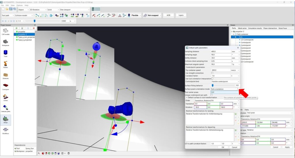
Option Path orientation. The tool keeps its orientation in Z and X and Y direction. It follows the the path along the curved surface. I.e. it maintains e.g. a 90 degree angle to the surface and if the path makes a turn, the tool makes a turn as well. This motion is demanding for the robot, but for several processes, such as belt-sanding, taping and cutting with a knife it is needed.
Landing-Departing / Approach-Depart Motion #
The generated tool path of the robot can be automatically extended by motions to approach to the main path and depart from the main paths
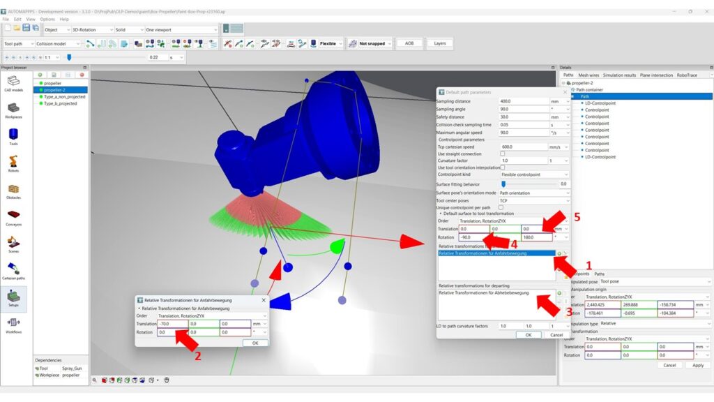
As shown in above image, you can add and modify the default settings for one or more “landing” and “departing points” (shown in the 3D view in gey – while control-points are blue) which are automatically added. This is done in the “transformation for landing” (1) and the “transformation for departing” (3). In the example above the added motion for “landing” (or approaching) is -70 mm in X direction (see 2), which is the direction of the path. Thus, the path is prolonged (starting 70mm before the first control-point). The motivation is that the tool will be precisely on the paths (even with blending) and will have reached desired speed at the first control-point, where e.g. the spray tool is turned on. (Note: you can add several points and turn of the spray earlier to compensate delays of the spray gun). At the departing, the setting in this example is +70mm in X direction. In this way, the path is prolonged by 70mm to achieve the tool is not deviating due to blending of the robot. For the example of grinding, especialls with compliant tools, you would have the Z value of landing and departing e.g. 50mm. In that way, the tool approaches until contact with the surface and starts transitioning to e air motion after been clearly not in contact with the surface anymore.
Please note: the coordinate system you see in the image above is 90 degree rotated to the path orientation, since this is the coordinate system ot the painting tool. It is rotated by 90 degree as you can see in the “surface to tool transform” (4). The 180 degree rotation around X (5) is needed since the TCP of the tool is pointing forward and shall point towards the surface while the normal vector of the surface points away from the surface.
More path parameters #
You can set more default values of the robot tool-paths which are automatically used in robot offline programming.
More information on these paramters is provided in the chapter “Settings and Parameters for Robot Offline Programming” / document: OLP- Path parameters.
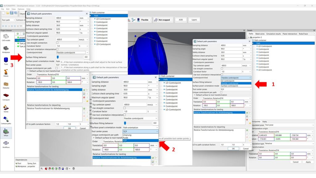
The image above shows 3 important settings:
- With the parameter “controlpoint kind” you can select amoung “air control points” which are used in paths that have less relation to the surface and connect the control-points in straight lines without following the shape or curvature of the part. a “surface control point” samples the path and strictly follows the surface of the path at that sampling-points with defined distance and orientation. If the surface is not smooth, the path is not smooth either. “Flexible controlpoint” is behaving like a surface control point if the sample is above the surface, and behaves as a “air control point” if there is no surface nearby against which the path can align itself.
- With “Tool center poses” you can select the TCP you want to use for the path (e.g. TCP1, TCP2, ..).
- The “surface fitting behavior” can be defined using a smooth transition between aligning the tool orientation to the surface orientation at each user-defined control-point and each automatically inserted (sampled) “way-point” (value 0) versus aligning only at “control-points” and interpolating inbetween.
More choices and settings as shown in the chapter Settings and Parameters – Path Parameters


