
Chosing suitable settings and parameters for paths minimized the effort you have to spend to adapt paths later, since generated paths will already consider these choices.
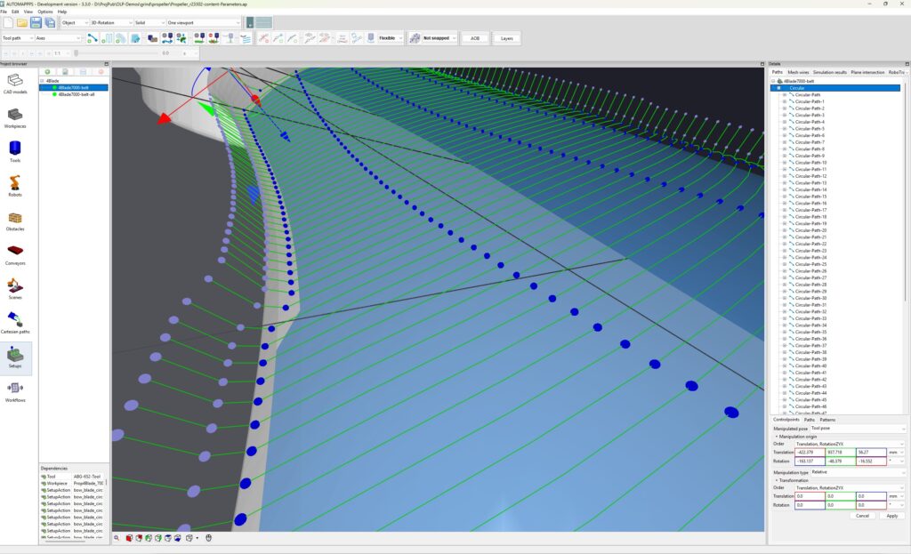
Robot tool paths are semi-automatically generated or added interactively by the operator. In any case, many properties of those paths shall be the same, e.g. how the approach the surface, what their distance and angle to the surface is etc. The default values can be set in the path parameters.
Getting started #
There are 3 ways and levels how to define the inital (default) settings of those paths.
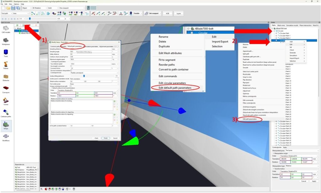
- You can “Modify the parameters of the setup” , go to default path parameters. Every new path created after these changes will adopt the new settings – except those paths which are under the “umbrella” of a meander or container or similar which can have own default path parameters (see 2)
- You can edit the “default path parameters” of a pattern such as a meander, or container. These patterns and containers can have their individual parameters. Any new aded path or and path that is generated if e.g. a meander is newly generated or projected will adopth those default parameters.
- You can edit the individual parameters of a selected path.
Overview of path parameters #
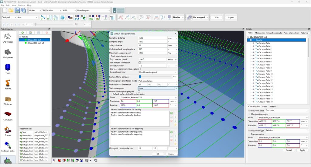
The image above shows all the path parameters. These will be explained in the following.
Tool orientation #
The tool orientation along the path, i.e. the behaviour / mode of the tool with respect to the surface of the part is defined in the “surface pose orientaion mode”. You can chose among the following mode / path following behaviours.
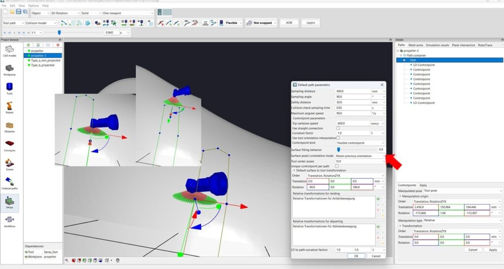
Option Retain previous orientation. The tool keeps or freezes – around Z- axis of the tool its orientation as well as this is possible with arbitrary motion. The tool orientaion in X and Y direction however follow the curved surface. I.e. it maintains e.g. a 90 degree angle to the surface. Please note, while this motion is best suited for the robot and reachabilty, it does work best for rotation invariant processes. A knife for example would break, and the spray gun shown above would need to be turned off ath the transition between updward and downward motion in order to not exceed the coating thickness.
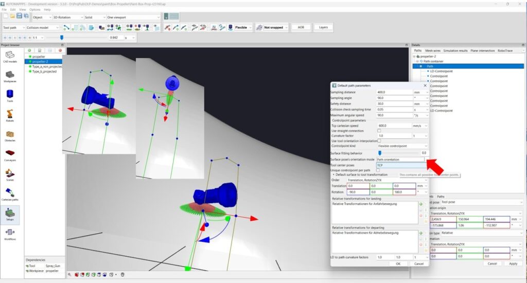
Option Path orientation. The tool keeps its orientation in Z and X and Y direction. It follows the the path along the curved surface. I.e. it maintains e.g. a 90 degree angle to the surface and if the path makes a turn, the tool makes a turn as well. This motion is demanding for the robot, but for several processes, such as belt-sanding, taping and cutting with a knife it is needed.
Landing and departing / approach-depart #
For paths which are either automatically generated by meanders or other patterns, or which are interatively defined (by clicking on the surface of the part to eb treated), it is common to have a short motion to approach this path or depart from it. The way it is approaching or departing is usually depending on the process or tool and thus the same for all paths.
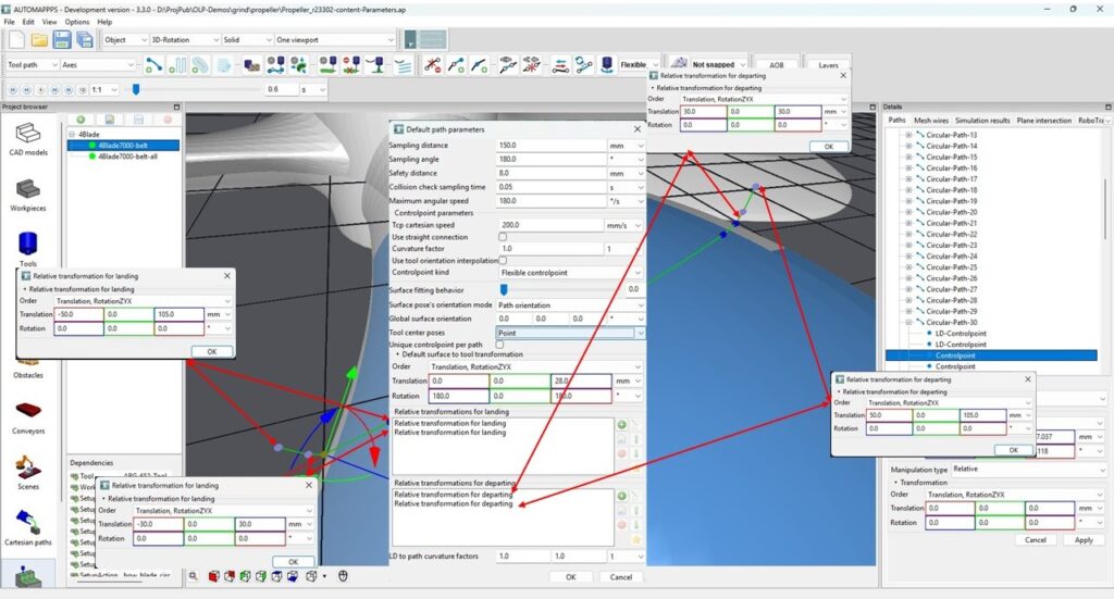
The image above shows how the Landing and Departing motions are defined. For landing, the upper relative transformation defined the outer point, following (0,1,2,..) transformation the more and more inner transformations. For the departing, the firsts transformation describes the departing point which succeeds directly after the control-point and the following transformatoin describe more and m,ore outer points. If the path shall be elongated or stretched, the X-value must be negative for the landing and positive for the departing.
More path parameters #
You can set more default values of the robot tool-paths which are automatically used in robot offline programming.
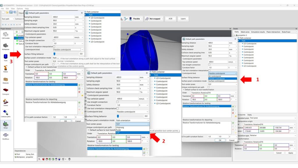
The image above shows 3 important settings:
- With the parameter “controlpoint kind” you can select amoung “air control points” which are used in paths that have less relation to the surface and connect the control-points in straight lines without following the shape or curvature of the part. a “surface control point” samples the path and strictly follows the surface of the path at that sampling-points with defined distance and orientation. If the surface is not smooth, the path is not smooth either. “Flexible controlpoint” is behaving like a surface control point if the sample is above the surface, and behaves as a “air control point” if there is no surface nearby against which the path can align itself.
- With “Tool center poses” you can select the TCP you want to use for the path (e.g. TCP1, TCP2, ..).
- The “surface fitting behavior” can be defined using a smooth transition between aligning the tool orientation to the surface orientation at each user-defined control-point and each automatically inserted (sampled) “way-point” (value 0) versus aligning only at “control-points” and interpolating inbetween.
More choices and settings as shown in the image:
- a) Sampling distance: the kartesian distance a part is sampled. If the length between 2 user-defined control-points exceeds the value, a way-point is inserted (and depending on the setting) the orientation of the surface at this point is used
- b) Sampling angle: If the orientation between 2 user-defined control-points changes more than the defiend value, a way-point is inserted.
- c) Safety distance: the minimum distance between tool and part. The check is performed in a given time interval.
- d) Collosion check sampling time. The time intervall the path is checked for collision between tool and part.
- e) Maximum angular speed: The planner reduces the kartesian / linear TCP speed automatically if the angular change exceeds the defined value. This is helpfull if e.g. the tool shall follow a corner and the resulting flange motion would be too fast for the robotl. This is the more important the longer the tool or TCP since angular motions lead to larger flange speeds.
- f) TCP cartesian speed: default path-speed of the tool-center-point.
- g) “Use straight connection” converts the tool path to straight lines between the suer-defined control-points
- i) “Curvature factor”: if the value is 1, the path is a spline, if the value is 0, the path is more a connection of linear motions. This refers only to the path-shape orthogonal to the surface. The path will follow the curvature of the surface anyway. If you want to supress this as well, selecte “use straight connetions” (see g)
- j) “Use tool orientation interpolation”. If true, the path orientation interpolates between 2 control-points in all dimensions.
- k) “Unique control-point per path”: The path is limited to one control-point. This is e.g. desired for patch-based visual inspection. The robot moves from one point to another in (faster) air motion.
- l) LD to path curvature factors: The 2 values desribe if the approach and depart motion of a curved path shall be curved as well or shall be straight.
Common Path Parameters #
In addition to the “Default Path Parameters” which descibe the behavior of the tool path on the surface, such as which TCP, wich distance, which angle, the “Common Path Parameters” deal with how to the surface is considered or sampled as a prestep to the “Default Path Parameters”.
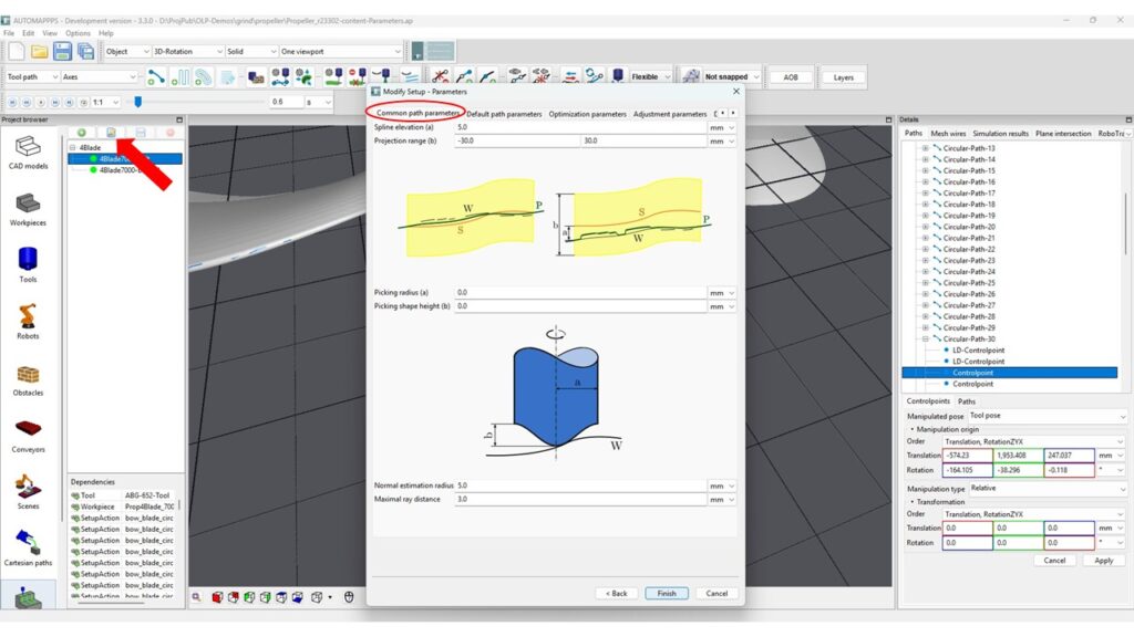
The default path parameters serve for influencing how the base-points of the future tool-paths are detected on the surface of the part. Parameters come in couples. The parameter-couples are
- “Spline Elevation” and “Projection Range”. Consider you have a perfect CAD, then you can all set to 0.0. However if the data are a bit noisy (such as reconstructed with a 3D sensor) or e.g. the opening angle can differ, your point might not hit the surface of the part. Therefore, the SW takes of the surface by the “Spline Elevation” and shoots rays in the lengths of “Projection Range” to hit the surface.
- “Picking radius” and “Picking shape height” can be interpreted as the needle of a record-player. If the rays are hitting e.g. a step in the surface, the value is not “jumping”, but smoothly transitionon and if there is a small gap in the data (smaller than the radius), the method can still find a value to project on.
- “Normal estimation radius” and “maximal ray distance”. The surface orientation is not determined at one single point but for a radius (unless the radius is 0.0). “maximal ray distance” mainly influence the number of rays that are used to determine that radius, thus influences speed and smoothness.


