CAD data belonging to parts and obstacles are loaded quite straight-forward as in more or less any CAD program. Specific obstacles shapes can be created e.g. by loading simple boxes, cylinders etc. and scaling them to the right lenght, width, height independently.
Supported file formats are: STEP, STL, IGES,
We recommend to use stl for obstacles as they are faster to load than STP by any CAD system. We also recommend to have low or medium resolution files for obstacles to speed up loading and collision-checks.
If you want to make use of edges or CAD features during later “programming” stages, you will have to use STEP or IGES for work-pieces, since STL does not contain CAD-features but pure mesh information.
The next video shows an example how to load a new object into the OLP SW – via loading and renaming a CAD file. The object can later be used to model the robot-cell or scene (1.7) built of different objects, robots, etc..
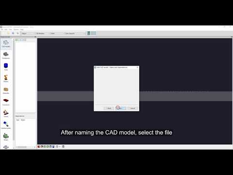
The video is embedded by YouTube and only loaded and played from there when you click on the play button. From then on, the privacy policy of Google applies.
After loading a CAD-file, you can manipulate it.
The next video shows how you can rotate a loaded part, or change its origin. Also scaling is shown, a feature not only for dealing with mm, m, inches, but also a simple way to create a wall or obstacle, starting with a CAD of a box, or cylinder, or plane.
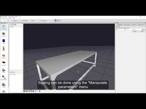
The video is embedded by YouTube and only loaded and played from there when you click on the play button. From then on, the privacy policy of Google applies.
Marking segments of the CAD surface #
If you want to process only a specific region of the part, or differnt regions, you can mark different segments of the mesh of a part.
- go to “Mesh segment”
- Add a new segment
- Load new segments
- duplicate a segment (and modify it later). This can also be done by <CTRL C>, <CTRL V>
- remove a segment (can also be done via <DEL> / <ENTF> a.s.o. key)
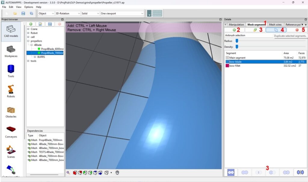
Image:
If you selected “Add new segment” in order to “mark/create” a segment of the mesh, you can chose amoung the following options (see 1)
- Airbrush: you can basically paint
- Flat area selection: click on any part of a flat area and all its triangle will be selected”
- Rectangular selection: rotate the part into a good pose. <CTRL> + <left mouse> click on any point in the image (even outside the part / CAD / mesh) and keep clicked. Move to any second point and the SW will show a reactangle untill you release the mouse.
- Polygon selection: <CTRL> + <left mouse> click several times on the border of the desired shape.
To un-select an area, to shrink the ares you have the same options, just use <CTRL> + <rigth mouse> button.
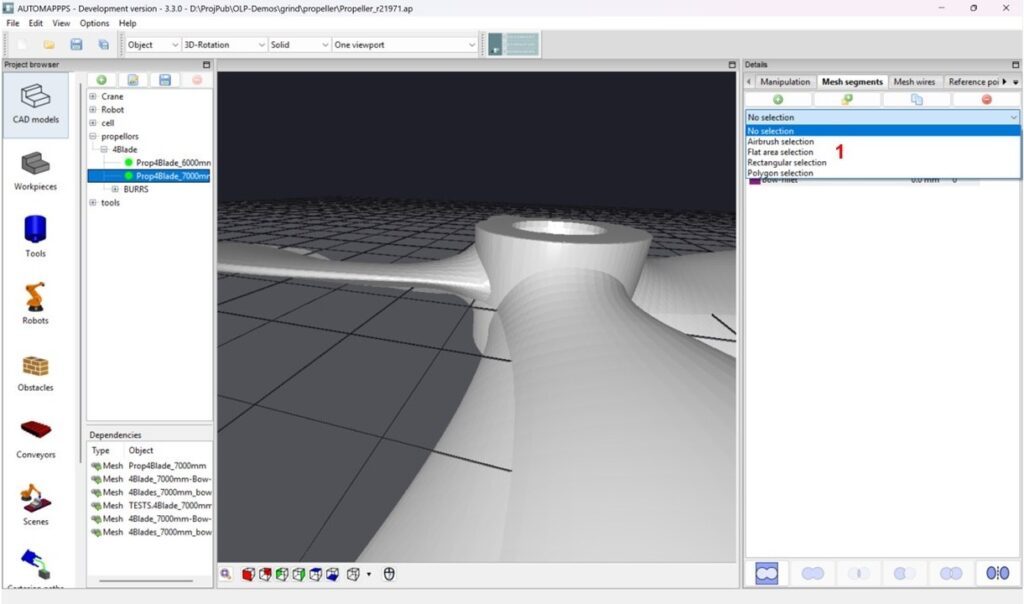
Image:
If you have selected e.g. the “Airbrush-selection”, define the size of the spray-radius (1) and the density (2) of the spray. For defining the outer contour of a mesh to be selected, chose a smaller radius, for filling the inner regions, chose a larger radius. If the CAD-mesh has fine triangles use a higer density.
You can create new meshes (3) by adding to already defined mehs regions, or select all the complementar area around on or two segments (i.e. all the area except the selected segment(s). There are several more options such as seleting the surface inbetween two segments. Hover above (3) to check out the options via the tool-tip.
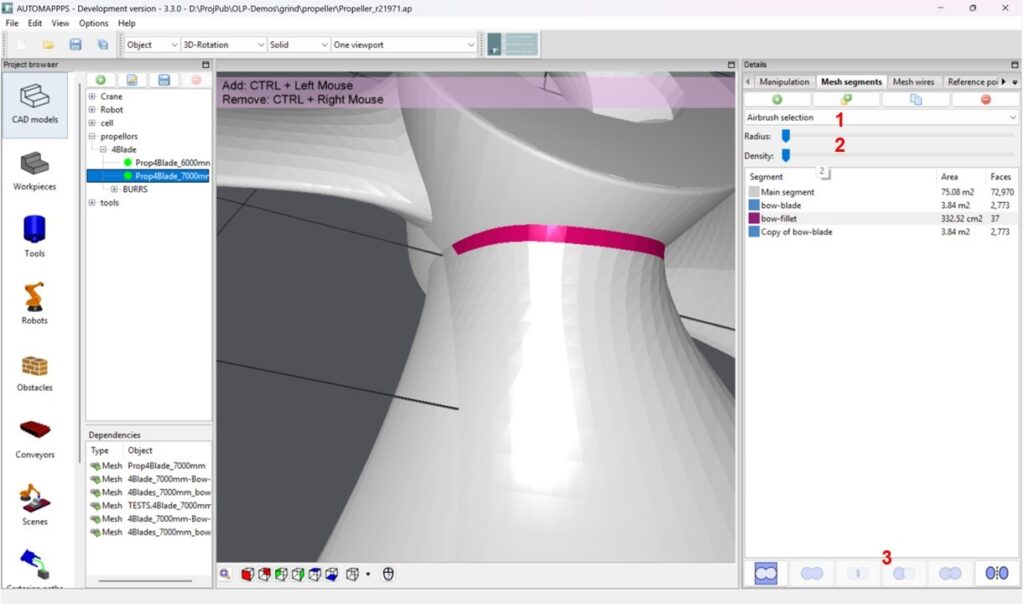
Image:


