This document describes how to build up a robot cell from the individual components such as robots, tools, parts and obstacles.
Preconditions: obstacles, robots, conveyors/axes, workpieces and tools have been created/imported
The video is embedded by YouTube and only loaded and played from there when you click on the play button. From then on, the privacy policy of Google applies.
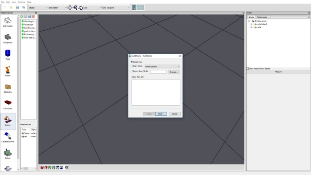
Step 1: create a new scene, i.e. commonly a workcell. Alternatives would be to copy one already existing in the same project/database or to import from another project / database. Assign a name to the scene.
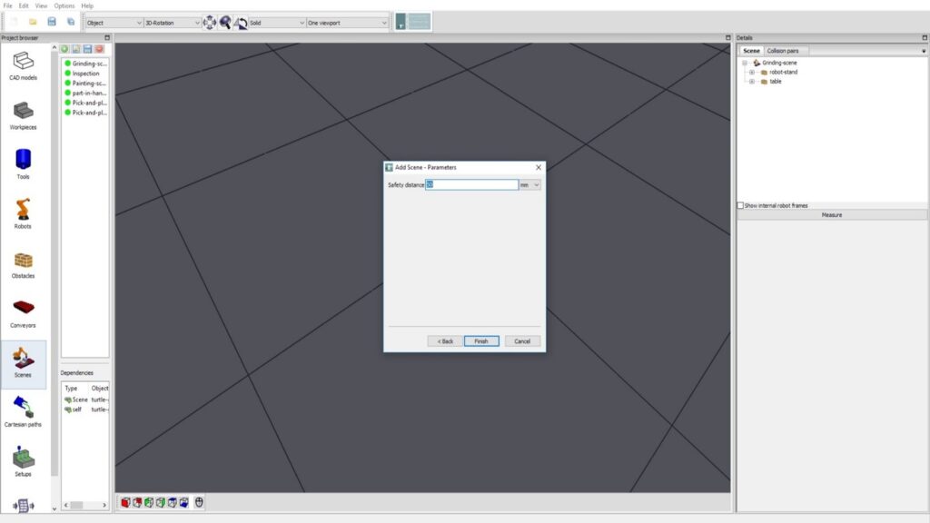
Step 2: Define one initial safety distance between entities in the scene, such as tools, robots, workpieces, obstacles against each others. Safety distances for specific entities –like tool vs. work-piece, can be changed individually later. Note: collision pairs, that can not collide in the scene, such as joints or bases of the robot against (remote) obstacles, or static obstacles against other ones, are set to [void] automatically.
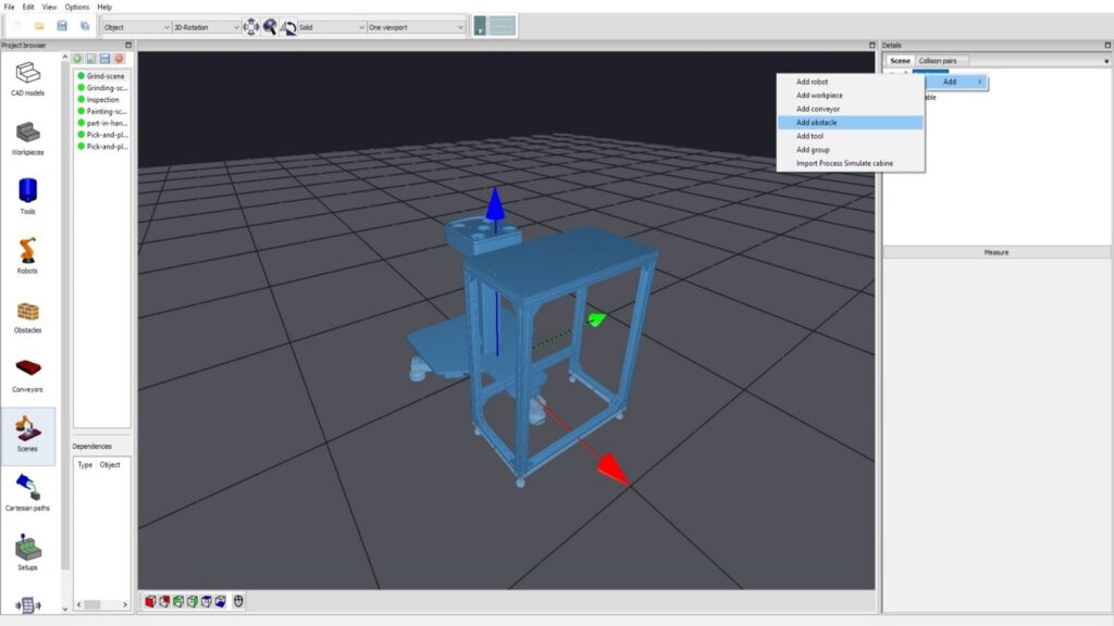
Step 3: Add elements to scene. Such as robots, obstacles etc. In the case of the image below, 2 obstacles have been added.
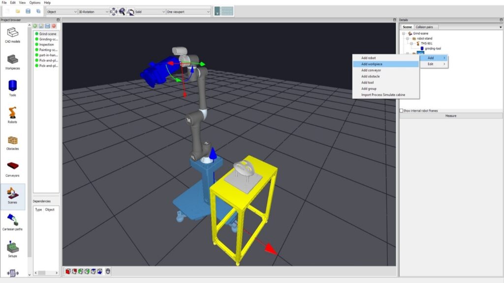
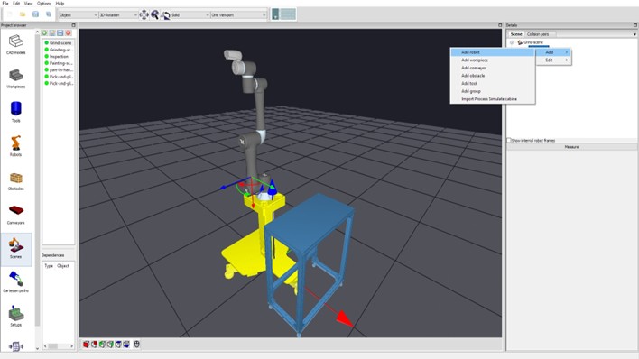
Step 4: Then add robot to the robot cart.
If you select the cart and then add the robot, it is assigned to the cart, and if the cart has a mounting point, the robot might be positioned correct right away. Potentially the robot (its base) must be re-posistioned. The base of the robot is not collison tested against the cart, since it is “connected” in the tree-representation.
If you still have selected the scene, the robot is added in the tree-representation to the scene, not to the cart.
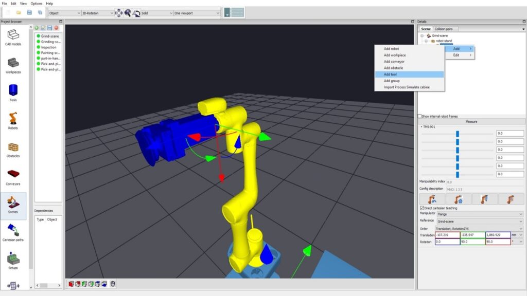
Step 5: Add the tool to the robot in tha same way —from the list of tools in the project. Note: the tool will by default be connected with its Flange-pose (if define) to the robots-flange. You can modify this transformation afterwards. For part-in-hand applications, the part is attached to the robot (with a gripper inbetween) and the tool is attached to an obstacle, table, etc.
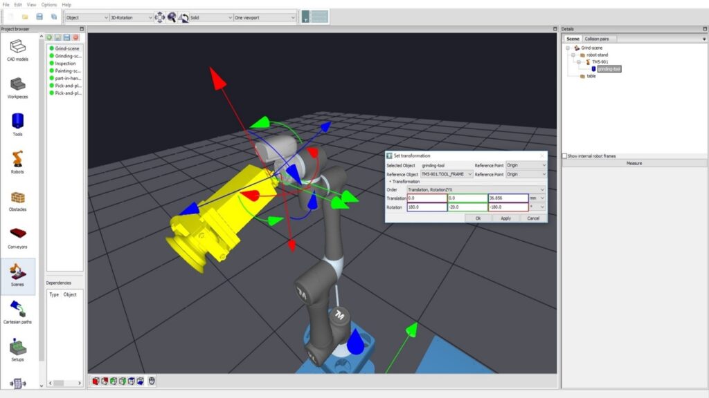
Step 5b: The orientation of the tool can be changed by edit -> set transformation. The defined transformation will be visualized after “apply” (alternatively after OK).
Step 6: Select the work-piece. Note the fist entity selected and added to the scene is initially attached to the scene- graph at the root. Assignments inside the hierarchy can be changed later in the scene graph by drag-and-drop.