This section gives you the fast introduction to the GUI, the entities and the usage of the mouse for interacting with the SW.
The following video shows the interaction with the contents vs. changing the view. If you want to change the view, use the mouse buttons as described after the vidoe in the image in “C”. If you want to interact with the content of the view, e.g. modify a pose or orientation of a part, of a tool-path, of the control-point: do the same with <CTRL> pressed … to be in control.
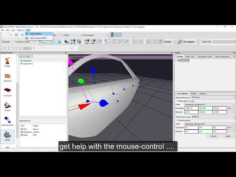
The video is embedded by YouTube and only loaded and played from there when you click on the play button. From then on, the privacy policy of Google applies.
The following image show the GUI at start – before any project (.ap file) is loaded.
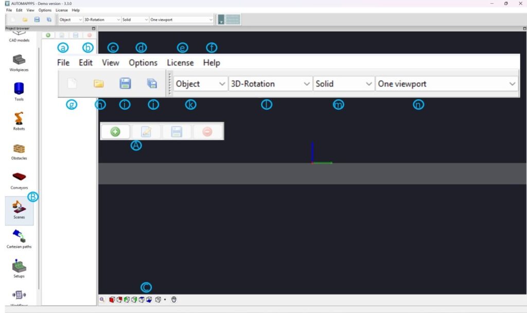
The individual GUI entities of the start screen are:
- a: general file-functions of windows/linux: “New Project” , “Open Project”, “Safe Project”….
- b: Edit functions for recent changes: “undo” and “redo”
- c: View functions to turn on/off the “sidebar” , “coordiante-system”, “grid-plane”, “rotation center” as well als “rendering modes” (foreground…), “visualization parameters” such as size of arrows, spheres, and transparency, show “path-names” on-off, or “path-visualization-mode” showing the control-points as coordinate systems or points.
- d: Options: So far language options: English, German, Chinese, Japanese
- e: License: Information for license update, especially remote or cloud license
- f: Help about mouse usage and AUTOMAPPPS revision, license detected, dongle detected etc.
- g-j: close project / open project / store project /store project as
- k: defines the view / camera navitation stile: object, camera or viewpoint-centered
- l: defines how the view rotates: 3D-rotation, spherical-rotation, Global X,Y,Z or Roll, Pitch, Yaw
- m: How the objects are rendered: solid, wire-frame or point-cloud
- n: select if you want to have 1,2,4 views of the area of interest
- A: Adding, editing, storing or deleting what has been selected in (B) the project browser
- B: Project browser – guides you through the steps of programming: From top down: “CAD editor“, to load/import, edit, manipulate CAD Data, “Work-piece Editor” to enrich a loaded CAD to become a workpiece to be treated, “Tool-Editor” to model tools with processes (simulation.model), flanges TCPs, and models for visualization and collision avoidance with different stages (e.g. open and closed grippers), “Robot -Editor” to import new robots and potentially limit the joints for all robots, “Obstacle-editor” to enrich a loaded CAD to become an obstacle, “Conveyor-Editor” to enrich a loaded CAD to become an 7th-axis (or 8th, 9th), rotation-table, conveyor etc., “Scene Editor” to assemble objects, obstacles, robots to robot-cells,”Cartesian-Path” for defining spacial approaching motions (very rately used by experts only), “Setup-Editor” to define and simulate tool-paths and processes, “Workflow-Editor” to assign tool-paths to robots and plan collision-free, singularity free etc… After a cell is designed, the real programming happens in “Setup-Editor” and “Workflow-Editor”
- C: Here you can select standard views, like from left, from top, stored preferences and you can zoom/fit to the object. Also the use of the mouse buttons for zooming etc. is explained.
X-Y-Z color coding:
in all windows and editors, the axes, coordinate systems, dialog fields to edit values, and preselected views you will find this consistent color-coding:
- red is X
- green is Y
- blue is Z
How to select and edit an entity – how to open an dialog of a entity:
You can select entities in the tree-view, such as meanders, paths, control-points of a path, but also graphical elements such as an “action” a “home-pose-configuration” etc. with the left mouse button. Once selected, use the right mouse button to open dialogs to deal with the entities (copy, move, rename, shift, etc…).
Several functions are also represented by explicit “buttons/logos” at the GUI. Here the dialog is opening already at the left click.


