The process result can be simulated in the setup and in the workflow.
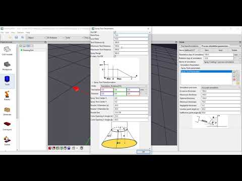
At first, select the process model for the simulation in the Tool-editor. Then define the process-parameter. E.g. for painting, one tool (spray-gun) can show different process settings (brushes). Therfore, you can define different sets per tool e.g. for painting. Select the point from which the simulation origins. Note: e.g. for painting, the painting-simulation starts at nozzle of the spray-gun, while the TCP commonly is 180-250mm (or more) in front of the nozzle.
It is most easy if you define the point where the process-simulation origins in the as reference-point in the CAD editor. Then you select this reference-point in the Tool-editor als simulation point.
The video does show how you can model a simple painting process for paint-thickness simulation.
The video is embedded by YouTube and only loaded and played from there when you click on the play button. From then on, the privacy policy of Google applies.


