This document explains how to make the virtual world identical to the real world. It describes how to match the part´s pose in the real and in the virtual world. That is to align the the part-robot transformation in the virtual cell as it is in the real cell. The procedure can be done for all objects inb the cell, but commonly only the relation of the robot to the part to be processed is modelled that preciseley. All other objects poses originates from CAD or Layout or is measured and larger safety distances are added.
Step 1: Measure the position of the calibration points in the real cell with the robot:
Select three points on your real workpiece which can be easily reached by the robot and which are not co-linear. The best would be if these points are sharp corners and therefore can be accurately approached by a probe tip tool. Equip your robot with a probe tip tool and take care that the tool center point is correctly defined. Move the robot with the tip of your tool to these three previously selected points. Write down the Cartesian position (which is calculated by the robot controller) for each of these three points. Now you have the X, Y and Z coordinates for these three points in the base coordinate system of the robot.
Step 2: Mark the points at the workiece inside AUTOMAPPPS:
Open the „CAD“ editor and select the model of your workpiece.
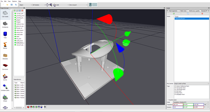
At the sidebar at the right side of the application open the „Reference Points“ tab. Press the „Add a reference point“ button for each of three calibration points. Assign a meaningful name to the added reference points like CalibrationPoint1, CalibrationPoint2 and CalibrationPoint3.
Change the transformation of the reference points in a way, that they match the positions of the workpiece you „touched“ with the robot in the real world before. This may be done by editing the position values of the translation text control elements of the Transformation widget or by using the object manipulator which is show in the 3D window when a reference is selected. And easier method is to set the „Control Mode“ parameter to „Snap to Vertex“ or „Snap to Mesh“. This allows you to specify the position of a reference point by clicking with the left mouse button and the CTRL key near the desired position of the part (the same as the robot touched) and the next CAD edge or vertex is selected.
Step 3: Include the poses measured by the robot into the scene in AUTOMAPPPS
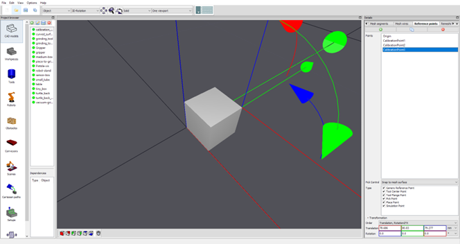
Add an arbitrary CAD object to the CAD models editor (e.g. a boy) which will be afterwards temporarily added to the scene. Again add three reference points to this CAD model and use a meaningful name for this reference points. As transformation of the reference points you insert the measured values you got from the robot controller. These are the transformations of the identical points of the parts (which have been marked in the CAD file) but measured in real world by the robot.
Step 4: Alignment of real-world and scene
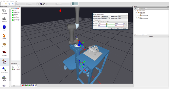
Select the corresponding scene. Temporarily add the newly generated obstacle (to which the measured points are added) to the scene. Change the position of this obstacle to the same position as the base coordinate system of the robot.
In the scene-tree select the entity of the workpiece with the right mouse button and select “Edit” -> “Align to”.
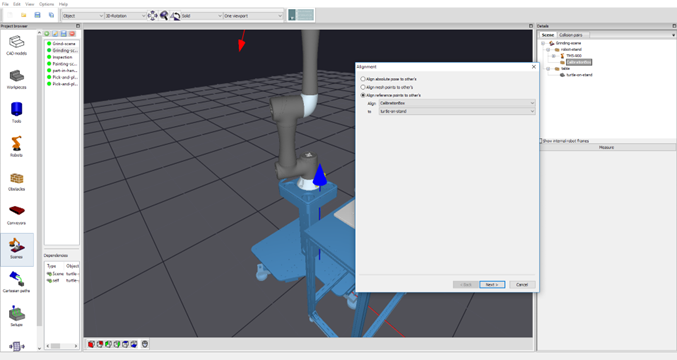
In the opened dialog select the „Align reference points to other’s“. In the „Align“ choice widget element the workpiece should already be selected. For the „To“ choice widget element select the newly added obstacle. Afterward press the Next button.
For the „Selected entity“ and the „Reference entity“ select the previously added reference points. Take care that the order of the selected reference points match. If all the reference points are given the Finish button is activated and have to be pressed.

If everything works fine the scene entity of your workpiece is correctly placed.


